
Introduction
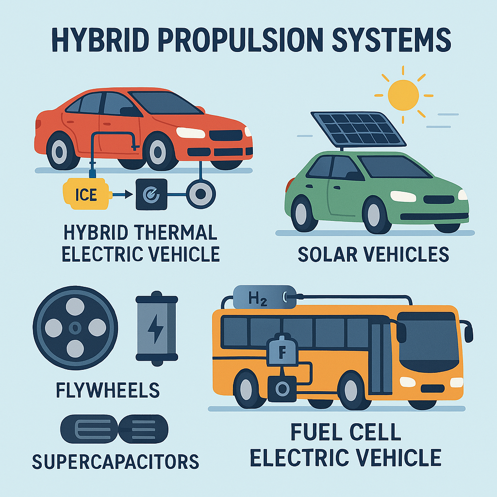
A hybrid propulsion system refers to any vehicle architecture that employs two or more distinct power sources to generate motion. The most common combinations involve internal combustion engines (ICE) coupled with electric motors and energy storage devices, such as batteries, fuel cells, or alternative systems like flywheels and supercapacitors. The motivation behind hybrid systems stems from the need to reduce fuel consumption, lower pollutant emissions, and improve efficiency in both private and public transport vehicles.
This article explores the fundamental concepts behind hybrid propulsion systems, focusing on battery usage, configurations such as series and parallel hybrids, and the integration of alternative storage solutions, including solar panels, supercapacitors, and hydrogen fuel cells. Emphasis is placed on configurations already in commercial use as well as less common experimental solutions.
1. Overview of Hybrid Vehicle Architecture
A generic hybrid vehicle is powered by at least two different energy sources on board. These energy sources may include internal combustion engines, electric motors, batteries, fuel cells, and other alternatives. The specific configuration of mechanical and electrical components defines how energy is distributed and utilized.
Among the crucial components of any hybrid system is the battery pack, which plays a central role in storing and supplying electrical energy. The battery must be designed to accommodate its duty cycle—namely, the depth and frequency of discharge—depending on the vehicle’s hybrid configuration.
For example, in configurations where the battery supports the primary energy source only during acceleration, hill climbing, or low-speed operation, the battery remains at a relatively stable state of charge. This means that deep discharges are rare, which contributes to a longer battery lifespan compared to pure electric vehicles or hybrids with small storage systems.
Conversely, vehicles with limited storage capacity require batteries capable of frequent recharging, especially during regenerative braking. Such systems benefit from batteries or storage units with high specific power, enabling fast energy intake.
2. Hybrid Thermal Electric Vehicles (HTEVs)
Hybrid Thermal Electric Vehicles are among the most commonly implemented hybrid systems. They combine an internal combustion engine, an electric motor/generator, and a battery pack. Two major configurations are typical for HTEVs:
2.1 Series Hybrid Configuration
In the series hybrid, the electric drive is the sole provider of mechanical traction. It is powered by:
- A rechargeable battery pack
- An electric generator driven by the ICE
- Or a combination of both
In this setup, the combustion engine does not directly drive the wheels. Instead, it serves as a generator to provide electricity. Both the generator and electric motor can recharge the battery. Moreover, during regenerative braking, the electric drive functions as a generator to capture and store kinetic energy.
This configuration is currently used in specific applications such as diesel-powered railway engines, ships, and specialized vehicles with an individual motor per wheel. The primary disadvantage is the energy loss due to the multiple conversion stages—from fuel to electricity to motion. However, the system’s simplicity and lower cost make it attractive for certain sectors.
2.2 Parallel Hybrid Configuration
In the parallel hybrid, the wheels can be powered by:
- The ICE alone
- The electric motor alone
- Or both systems simultaneously
In this setup, the battery is typically recharged only through the electric drive, not the ICE. Regenerative braking is employed to recover energy into the battery, enhancing overall efficiency.
The key advantage of this configuration is the diversity of energy flow. Either source can propel the vehicle, reducing the size and cost of individual components, as each is only partially responsible for total output. Furthermore, operational modes vary:
- Full electric drive: When the ICE is switched off—ideal for urban zones with pollution restrictions.
- Thermal drive only: When batteries are disengaged—suitable for highway cruising.
- Combined operation: Both systems contribute to optimize emissions and fuel economy.
The “degree of hybridization” (DOH) quantifies the hybrid configuration using the formula:
DOH=Power of Electric MotorPower of Electric Motor + Power of IC Engine\text{DOH} = \frac{\text{Power of Electric Motor}}{\text{Power of Electric Motor + Power of IC Engine}}DOH=Power of Electric Motor + Power of IC EnginePower of Electric Motor
A high DOH indicates a small ICE operating at its optimal efficiency point, supported by a powerful electric motor.
Manufacturers often propose several variations of parallel configurations. Some place an electric machine in line with the crankshaft, while others use different axles for the ICE and electric motor (e.g., ICE on front wheels, electric on rear). In these cases, road connection allows the ICE to support battery charging indirectly.
Hybrid systems also allow external charging from the grid or other sources, while the vehicle is parked.
2.3 Cost and Design Considerations
Hybrid thermal vehicles are typically more expensive than conventional vehicles due to the complexity of multiple energy sources. However, they eliminate some traditional components:
- Series hybrids do not require a gearbox or differential when motors drive the wheels directly.
- Starters are unnecessary since electric motors handle ignition tasks.
Despite the added cost, market adoption is growing steadily due to environmental and regulatory pressures.
3. Solar Vehicles
Solar vehicles utilize onboard photovoltaic panels to capture solar energy and convert it into electricity. Although solar panels are becoming more efficient and less costly, using them as the sole source of propulsion remains impractical due to:
- The large surface area required to generate sufficient power
- The dependency on high sunshine conditions
However, solar panels can be used to maintain the battery charge in electric or hybrid vehicles. The configuration includes:
- Photovoltaic panel
- DC–DC converter to match the panel output with battery voltage
- Rechargeable battery
- Electric drive with DC–AC conversion
The DC–DC converter is monodirectional, meaning no energy flows back from the battery to the solar panel.
4. Vehicles Using Flywheels and Supercapacitors
Alternative energy storage systems such as flywheels and supercapacitors are also employed in hybrid configurations.
4.1 Flywheels
Flywheels store kinetic energy mechanically by spinning at high speeds. They are especially suitable for city trams or buses, where:
- The flywheel is charged by an electric motor during stops
- Regenerative braking transfers kinetic energy to the flywheel
Flywheels may be combined with batteries, reducing battery weight and improving system efficiency.
4.2 Supercapacitors
Supercapacitors offer very high specific power and rapid charge-discharge cycles. Their integration with batteries allows:
- Efficient regenerative braking
- Delivery of power surges during rapid acceleration
These storage units enhance battery management and can be used in various hybrid configurations alongside:
- Batteries
- Fuel cells
- Solar panels
- IC engines
The possibilities for combining such systems are broad and diverse.
5. Fuel Cell Electric Vehicles (FCEVs)
Fuel Cell Electric Vehicles combine a hydrogen fuel cell system (FCS) with electric motors and energy storage. This setup is complex, involving:
- Electric converters
- Fuel storage
- Auxiliary systems
Although the FCS could, in theory, supply all power needs, doing so requires:
- A high-power FCS stack (matching the peak power of the electric drive)
- The ability to handle rapid load variations
This approach is costly and technically challenging. As a result, most FCEVs adopt hybrid architectures:
5.1 Soft Hybrid Configuration
- FCS delivers most of the energy
- A small battery handles startup, auxiliary loads, and peak demands
- Benefits: minimal battery use and good performance during regenerative braking
5.2 Hard Hybrid Configuration
- FCS provides base load
- A larger battery manages high acceleration demands
- Ideal when the driving cycle is predictable with lower average power than peak demands
Supercapacitors are often used to handle fast power demands due to their high efficiency and specific power. In advanced configurations, batteries and supercapacitors are combined with a three-way converter to manage the interaction between devices.
Conclusion
Hybrid propulsion systems are a foundational element in the evolution of sustainable mobility. By combining traditional combustion engines with electric drives and innovative storage solutions such as flywheels, supercapacitors, and hydrogen fuel cells, engineers can build vehicles that balance performance, efficiency, and environmental responsibility.
Whether in the form of HTEVs, solar-assisted designs, or fuel cell hybrids, hybrid systems offer flexibility and scalability across a wide range of applications—from passenger cars to buses, trams, and ships. As technological development continues, the role of hybrid propulsion systems will become increasingly vital in achieving global transportation sustainability goals.
Leave a Reply